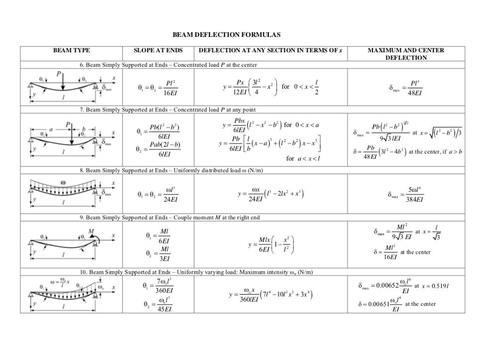
Deflection Formula For Cantilever Beam Step By Step Proof Youtube This video shows the derivation of deflection formula for cantilever beam step by step. it includes integration of moment to find out the slope, after findin. Cantilever beam equations. there are a range of equations for how to calculate cantilever beam forces and deflections. these can be simplified into simple cantilever beam formula, based on the following: cantilever beam deflections. taken from our beam deflection formula and equation page. cantilever beam equations can be calculated from the.

Cantilever Beam Deflection Formula S Youtube Example cantilever beam with single load at the end, metric units. the maximum moment at the fixed end of a ub 305 x 127 x 42 beam steel flange cantilever beam 5000 mm long, with moment of inertia 8196 cm 4 (81960000 mm 4), modulus of elasticity 200 gpa (200000 n mm 2) and with a single load 3000 n at the end can be calculated as. m max. A cantilever beam shown in figure 7.10a is subjected to a concentrated moment at its free end. using the moment area method, determine the slope at the free end of the beam and the deflection at the free end of the beam. \(ei\) = constant. \(fig. 7.10\). cantilever beam. solution (\(m ei\)) diagram. 9.2 differential equations of the deflection curve. consider a cantilever beam with a. concentrated load acting upward at the free. end the deflection v is the displacement. in the y direction. the angle of rotation of the axis. (also called slope) is the angle between the. x axis and the tangent to the deflection. 2. cantilever beam – concentrated load p at any point 2 pa 2 e i lei 2 3for0 px yax xa 6 ei 2 3for pa yxaaxl 6 ei 2 3 pa 6 la ei 3. cantilever beam – uniformly distributed load (n m) 3 6 l e i 2 22 64 x yxllx ei 4 max 8 l e 4. cantilever beam – uniformly varying load: maximum intensity o 3 o 24 l e i 2 32 23 o 10 10 5 120 x yllxlxx 4 o.
Solved Determine The Deflection Equation Of The Cantilevered Beam 9.2 differential equations of the deflection curve. consider a cantilever beam with a. concentrated load acting upward at the free. end the deflection v is the displacement. in the y direction. the angle of rotation of the axis. (also called slope) is the angle between the. x axis and the tangent to the deflection. 2. cantilever beam – concentrated load p at any point 2 pa 2 e i lei 2 3for0 px yax xa 6 ei 2 3for pa yxaaxl 6 ei 2 3 pa 6 la ei 3. cantilever beam – uniformly distributed load (n m) 3 6 l e i 2 22 64 x yxllx ei 4 max 8 l e 4. cantilever beam – uniformly varying load: maximum intensity o 3 o 24 l e i 2 32 23 o 10 10 5 120 x yllxlxx 4 o. A cantilever beam shown in figure 7.10a is subjected to a concentrated moment at its free end. using the moment area method, determine the slope at the free end of the beam and the deflection at the free end of the beam. ei = constant. fig. 7.10. cantilever beam. solution (m ei) diagram. Show that, for the end loaded beam, of length l, simply supported at the left end and at a point l 4 out from there, the tip deflection under the load p is pl3 given by ∆= (316 ⁄ )⋅ ei p a b c l 4 l the first thing we must do is determine the bending moment distribution as a function of x. no problem.

Deflection Of Cantilever Beam Carrying Moment Double Integration A cantilever beam shown in figure 7.10a is subjected to a concentrated moment at its free end. using the moment area method, determine the slope at the free end of the beam and the deflection at the free end of the beam. ei = constant. fig. 7.10. cantilever beam. solution (m ei) diagram. Show that, for the end loaded beam, of length l, simply supported at the left end and at a point l 4 out from there, the tip deflection under the load p is pl3 given by ∆= (316 ⁄ )⋅ ei p a b c l 4 l the first thing we must do is determine the bending moment distribution as a function of x. no problem.

Cantilever Beam Deflection Formula Table Elcho Table

Comments are closed.