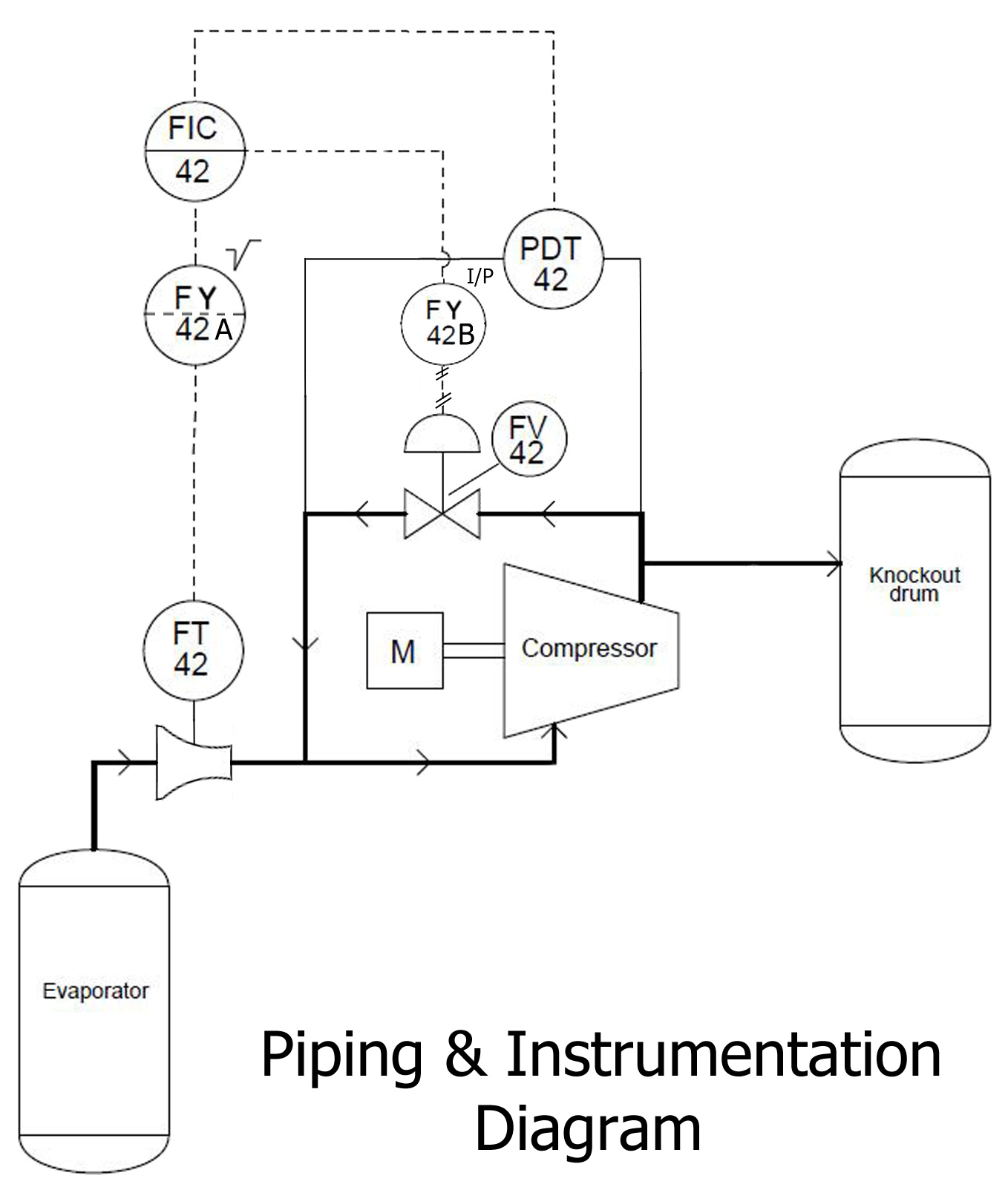
Example P Id Piping And Instrumentation Diagram Schem Vrogue Co The p&id, also known as the piping and instrumentation diagram, is an end to end schematic that displays major process details of a system. p&ids show operating conditions, major equipment, valves, and instrumentation required to run, monitor, and control a specific process. it is typically the first major deliverable for an equipment provider. A piping & instrumentation diagram (p&id) is a schematic layout of a plant that displays the units to be used, the pipes connecting these units, and the sensors and control valves. standard structures located on a p&id include storage tanks, surge tanks, pumps, heat exchangers, reactors, and distillation columns.

Example P Id Piping And Instrumentation Diagram Schem Vrogue Co A p&id drawing serves as a guide for start up and operational data. it is the basic training document to explain the process details to operation guys, field engineers, and maintenance professionals. the p&id drawings help them to track the interconnection between the piping and instrumentation and equipment. The piping and instrumentation diagram (p&id) is a graphical representation of the actual process plant using various symbols that represent actual equipment. it is a detailed diagram in the process industry that shows all piping including physical sequences of branches, reducers, valves, equipment, instrumentation and control interlocks. Schematic illustration of a functional relationship between piping, instrumentation and system components. p&id's shows all piping including physical sequences of branches, reducers, valves, equipment, instrumentation and control interlocks. the p&id's are used to operate process systems. p&id diagram online drawing tool. a p&id should include:. Piping and instrumentation diagram (p&id) is a schematic representation of a process flow between all process units or equipment's in a plant. as the name suggests the graphical representation on a p&id includes all piping connected between equipment's and the associated instrumentation necessary to design, construct and operate a plant.

Example P Id Piping And Instrumentation Diagram Schem Vrogue Co Schematic illustration of a functional relationship between piping, instrumentation and system components. p&id's shows all piping including physical sequences of branches, reducers, valves, equipment, instrumentation and control interlocks. the p&id's are used to operate process systems. p&id diagram online drawing tool. a p&id should include:. Piping and instrumentation diagram (p&id) is a schematic representation of a process flow between all process units or equipment's in a plant. as the name suggests the graphical representation on a p&id includes all piping connected between equipment's and the associated instrumentation necessary to design, construct and operate a plant. In this video, you will learn the basics of piping and instrumentation diagrams (also called p&id drawings).#pipingandinstrumentation #processcontrol #instru. Section four: piping and instrumentation diagrams • identify when a piping and instrumentation diagram would be required • identify the specific sections of the p and id’s • identify the drawing history • identify the drawing number and title • illustrate the design and creation of a typical p and id. section five: reading process.

Comments are closed.