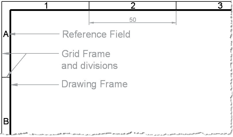
Technical Drawing Standards Grid Reference Frame Grid references. the grid references start from the top left of the sheet, with letters running vertically from the top down and numbers running horizontally from left to right. on an a4 sheet the grids only need to be drawn on the top and left hand side. the letters i and o are not used – because they could be confused with 1 and 0. Labelling a drawing and having the text on the drawing can clutter the information. make sure you keep the labels aligned and slightly away from the drawing to keep things clear. if you are using arrows, try to keep them all at the same angles. a good option is vertical, horizontal and 45 degree angle only if possible.

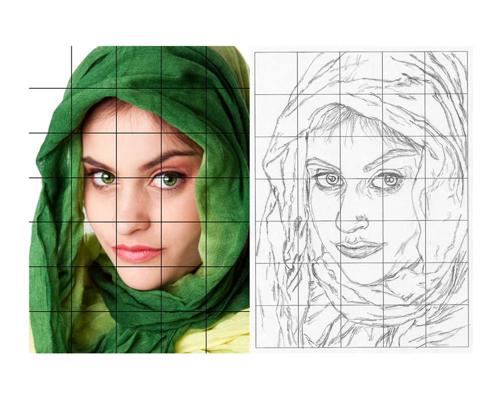
How The Grid Drawing Method Will Make You Have Improved Art Let S In order for structural drawings to fit on a manageable sized drawing sheet, the drawing is usually a small fraction of the real world size. a scale of 1:100 is a very common scale to use for a structural framing plan. that is, a 1mm measurement taken on the drawing represents a 100mm length of the real world object. How to read structural elements notation using a grid on structural drawings. how to reference columns and beams on a floor plan.#structuraldrawings #gridref. Technical drawing: plans. in part one of our technical drawing series we looked at layout, and part 2 explored labelling and annotation. in this part of the technical drawing series, we will look at plans. depending on the nature and complexity of a project, the floor plan can contain simple or complex information. In a standard set of architectural plans on a small residential project, the elevations will most likely be a set of drawings from the main facades of the building. for example, front, back and two sides – or north, south, east and west. the sections would most likely be two or more sections cut at 90 degrees of one another to give.

Comments are closed.