Installing And Calibrating An Outboard Tachometer Youtube In this video i install an tachometer in my boat. i wire up the power and then select the number of pulse or cycles my outboard has to get the correct readin. Join the community on discord: discord.gg efazn7eyce in this video i go over how to install, setup and use an outboard induction tachometer tiny tac.

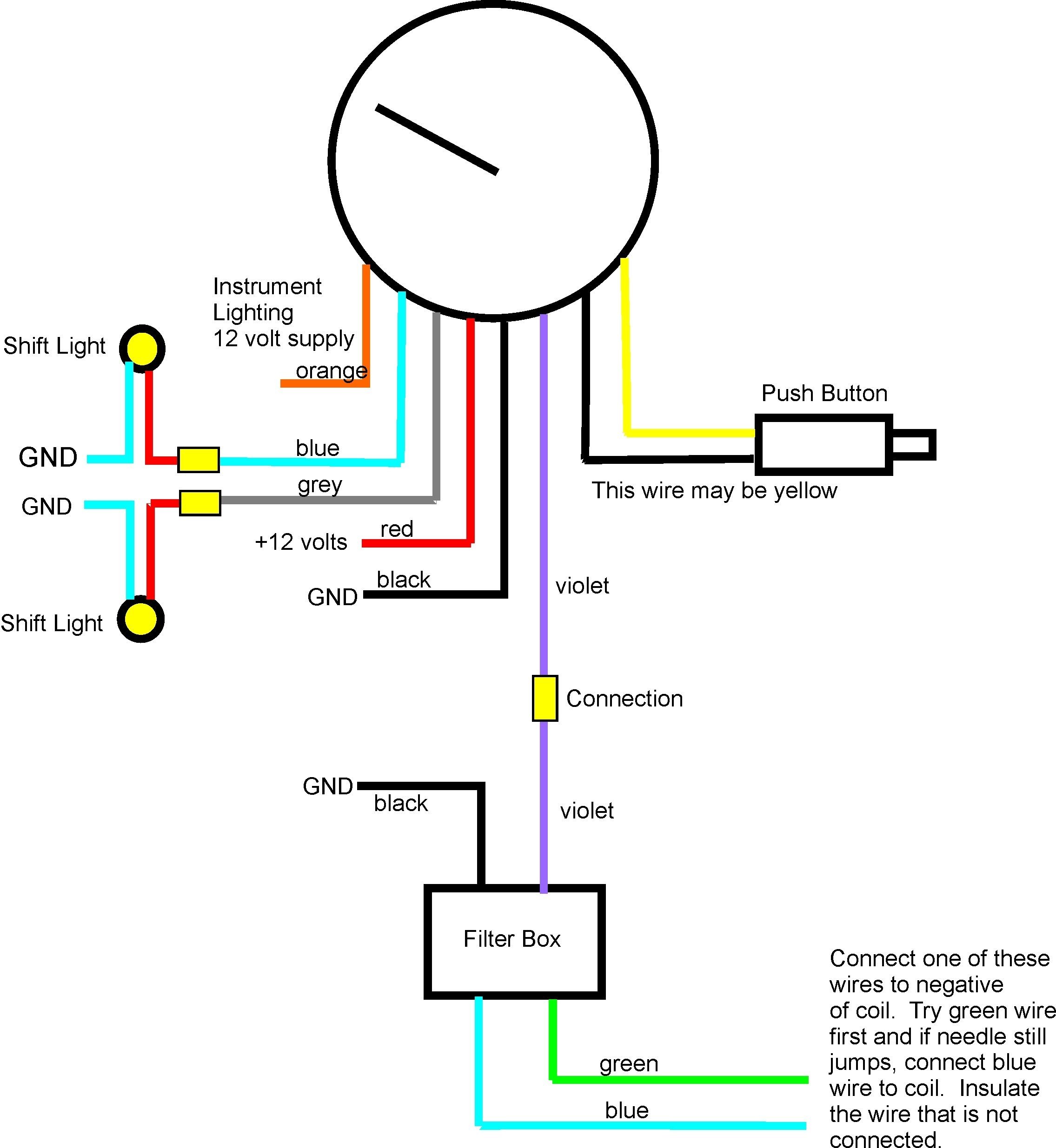
Install Tachometer Mercury Outboard Ways to test a tachometer on a boat. how to test and troubleshoot a boat tachometer. 1. perform initial assessments and diagnostics. 2. locate the tachometer’s signal source then check the signal voltage. 3. inspect the tach’s wiring. 4. Here is a basic wiring diagram for a mercury outboard tachometer: connect the red wire from the tachometer to the ignition switch’s “12v ” terminal. this wire provides power to the tachometer. connect the black wire from the tachometer to the engine ground or a common grounding point. This "how to" video will demonstrate the step by step process of installing a tach hour meter on an outboard marine motor. the tachometer is useful if you. So we're going to take this out to the bench and we'll make up some wires for now then we'll do the full install. two wires from the tachometer are going to go to the four controls. now the loom comes from the outboard to the forward controls and then several wires come back out.

Installing And Calibrating An Outboard Tachometer 41 Off This "how to" video will demonstrate the step by step process of installing a tach hour meter on an outboard marine motor. the tachometer is useful if you. So we're going to take this out to the bench and we'll make up some wires for now then we'll do the full install. two wires from the tachometer are going to go to the four controls. now the loom comes from the outboard to the forward controls and then several wires come back out. The wiring diagram will show how these components are connected to each other and to the outboard’s power source. step 4: trace the wires. using the wiring diagram as a guide, trace the paths of the wires involved in the tachometer circuit. pay close attention to the connections and ensure that they are correctly made. Step 5: connect the tachometer’s signal wire. connect the purple wire from the tachometer to the purple wire on your outboard motor’s ignition coil. this wire will carry the signal from the ignition coil to the tachometer, allowing it to display the engine’s rpm. step 6: secure and test the connections.

Installing And Calibrating An Outboard Tachometer 41 Off The wiring diagram will show how these components are connected to each other and to the outboard’s power source. step 4: trace the wires. using the wiring diagram as a guide, trace the paths of the wires involved in the tachometer circuit. pay close attention to the connections and ensure that they are correctly made. Step 5: connect the tachometer’s signal wire. connect the purple wire from the tachometer to the purple wire on your outboard motor’s ignition coil. this wire will carry the signal from the ignition coil to the tachometer, allowing it to display the engine’s rpm. step 6: secure and test the connections.

Comments are closed.