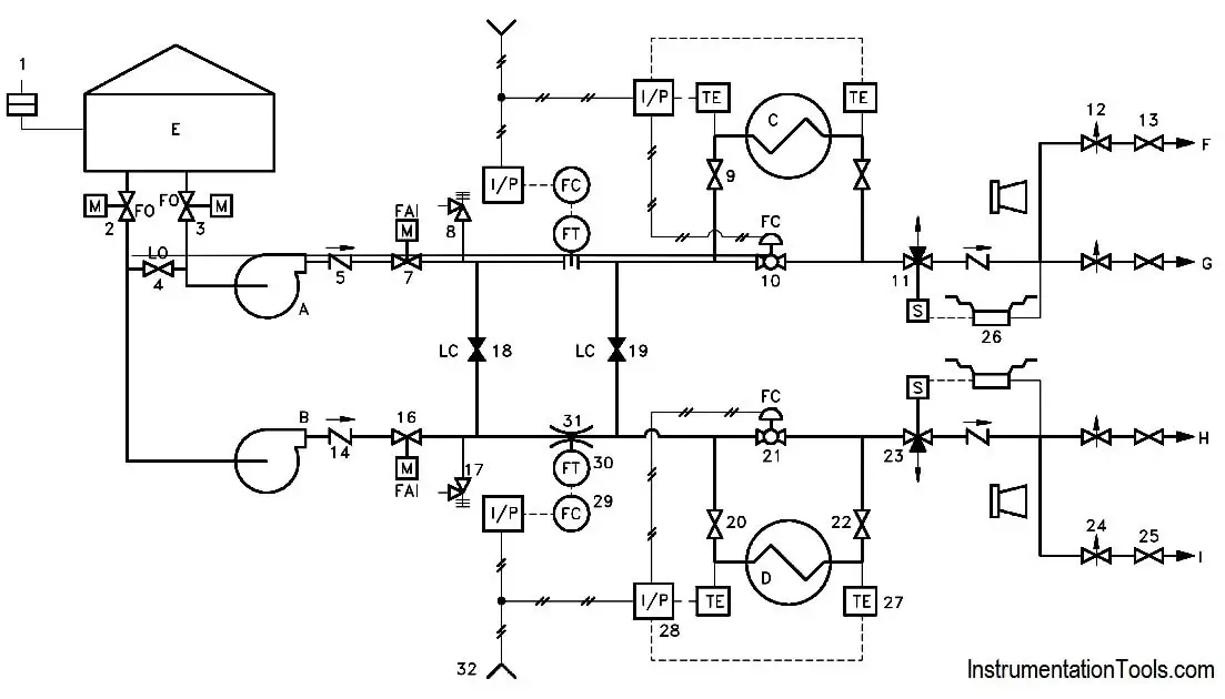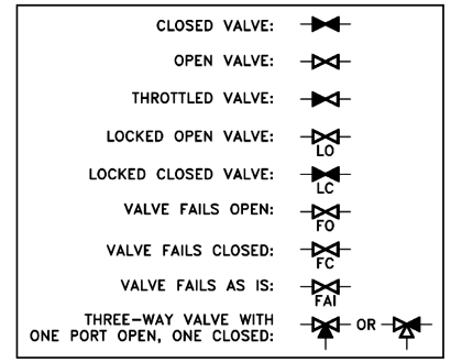
P Id Document Reading Example Instrumentation Tools P&id document reading example. example : at this point, all the symbols for valves and major components have been presented, as have the conventions for identifying the condition of a system. refer to figure 18 as necessary to answer the following questions. the answers are provided in the back of this section so that you may judge your own. Piping and instrumentation drawing (p&id) tutorials – part 1. by editorial staff. a through knowledge of the information presented in the title block, the revision block, the notes and legend, and the drawing grid is necessary before a drawing can be read. this information is displayed in the areas surrounding the graphic portion of the drawing.

P Id Document Reading Example Instrumentation Tools To read our blog on this topic, pls visit our website: instrumentationacademy p id how to read pid drawing easily piping instrumentation diagr. Piping and instrument drawings (p&ids) p&ids are usually designed to present functional information about a system or component. examples are piping layout, flowpaths, pumps, valves, instruments, signal modifiers, and controllers, as illustrated in figure 6. figure 6 : example p&id. as a rule p&ids do not have a drawing scale and present only. Reading p&id is difficult for those who start their careers in oil &gas and similar chemical process industries. here, i have tried to explain p&id and pefs in an easy way. the piping and instrumentation diagram is also known as the process engineering flow scheme, pefs. you will learn how to read p&id and pefs with the help of the actual plant. Now that we know our device fv01 is represented by a circle, we can also tell from the p&id where the instrument or device is located. the presence or absence of a line in the circle determines the location of the physical device. let’s take a look at how these are commonly represented. – no line: the instrument is located in the field near.

Comments are closed.